PhysicsGuy
Wimshurst Generators: Secrets in the Dark
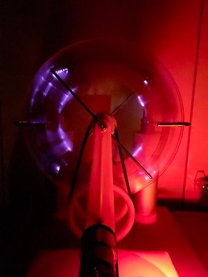 |
Long exposure photographs of Wimshurst generators taken in the
dark reveal how they work and provide valuable insights into perfecting
electrostatic generators and motors. The Wimshurst machine was first described
in 1883. Despite its age and popularity, descriptions of how they work are often
incomplete. As such, various components including sector shape and spacing,
charge collector geometry, neutralizer bars, and discharge ball size, have evolved
over time somewhat by trial and error. A better understanding of how these
generators work can lead to better designs. Long-exposure photographs taken in the dark
reveal plasma conduction paths and other processes that shed light on how to
improve generator performance.
The following publications give a good and relatively-modern summary
of experiments and observations.
1. Operation
of the Wimshurst Machine
Last updated: 2018 Dr.
Antônio Carlos M. de Queiroz
COPPE/UFRJ - Programa de Engenharia
Elétrica,CP 68504,21941-972 Rio de Janeiro, RJ, Brazil
2. Homemade Lightning, Creative
Experiments in Electricity, 1996 by R.A.Ford
3. A double
Wommelsdorf condenser machine
|
Publication 1 states: “The
Wimshurst machine is an "influence machine", an electrostatic
generator that uses the charges already present on it to generate more charges
by electrostatic induction.” Long exposure photographs of a working
Wimshurst generator taken in the dark reveal there is much more going on than
just electrostatic induction. The generator produces plasma due to corona
discharge. This creates conduction paths that charge the ends of the
neutralizer bars. These conduction paths also lose energy and can limit the
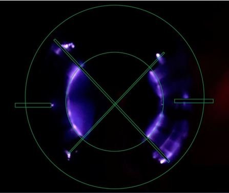
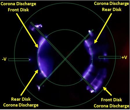
voltage output of the generator. The following long exposure picture of sparks
and corona discharge reveal the location of these conduction paths.
 |
 |
| Figure 1. This 30 second, ISO 3200 picture taken with
an Android smart phone shows the location of the corona discharge conducting
paths in a Wimshurst generator. The green lines show the position of the charge
collectors on the left and right, the position of the neutralizer bars and the
inside edge of the sector plates. |
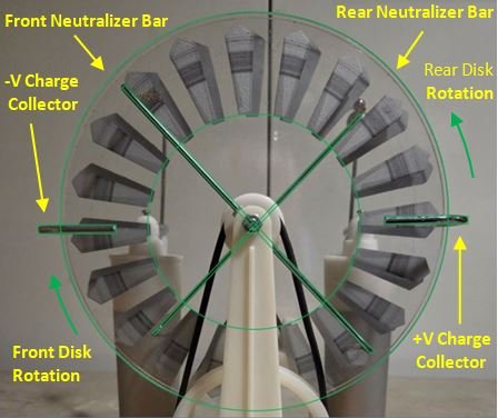
Figure 2. The position of the charge collectors, neutralizer bars and sector plates are shown
in this picture taken with the room lights on. |
Figure 1 and 2 contain a wealth of information about how a
Wimshurst generator works. Typical descriptions describe how the Wimshurst
self-charges through induction across the front and rear sector plates. See
Figure 5. Wikipedia, for example, describes this self-charging process, but
states that it is not enough to explain the high voltages that are actually produced. A
second process is needed that involves the potential difference across the left
and right charge collectors. This paper describes that process in more detail. The
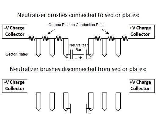
large potential difference across the charge collectors charges the ends of the
neutralizer bars. The corona discharge pattern in Figure 1 reveals how conductive
plasma forms between the inner radius of the sector plates and how these
conductive paths charge the ends of the neutralizer bars.
 |
 |
| Figure 3. This long exposure picture reveals which
side the corona discharge paths occur on. Plasma on the rear disk has a
slightly smaller radius. Also the front neutralizer bar blocks light from the
plasma on the front disk while the rear bar does not. |
Figure 4. Plasma on the rear disk has a slightly smaller radius.
Also the front neutralizer bar blocks light from the plasma on the front disk
while the rear bar does not.plates and when they lose contact with the sector
plates leaving a charge on the plates. |
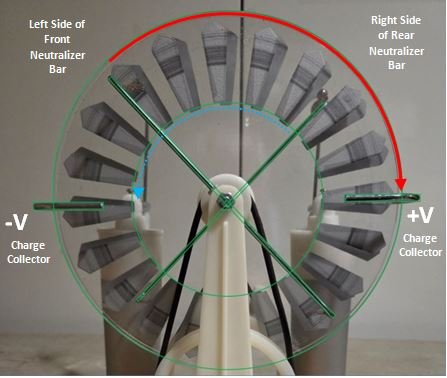 |
Figure 5. Typical descriptions describe how the Wimshurst uses charging
by induction through the front and rear sector plates. The front sector plates
near the red curve shown here must be positively charged to charge the right positive
collector. They gain their charge at the front neutralizer bar on the left and
lose their charge at the right collector. These positively charged plates
induce a negative charge on the adjacent rear sector plates when the brush on
the right rear neutralizer bar touches a rear plate. This is shown with the dashed
blue curved arrow. The arrow shows where they become charged and where they
lose their charge at the negative charge collector on the left. The capacitance
between these plates is not enough to explain how the Wimshurst produces such
high voltages so a second process must be occurring.
|
By understanding how the Wimshurst works, we can optimize the various
Wimshurst components for various design goals. Do we want the highest possible
voltage, or highest current or the best efficiency? These components include: sector
geometry, charge collectors, neutralizer bars, disk size, discharge ball size
and inherent asymmetry. Two of these, the charge collectors and inherent
asymmetry are described here. Others will be described in future publications.
The
Remarkable Design of the Charge Collectors
The charge collectors on
the sides of the Wimshurst can be seen as Faraday cages. They function in the
same way as a Van De Graff generator. When a charged sector plate enters the
center of the cage, charges on it will escape to the outside surface of
the cage further increasing its voltage. See Figure 6. It is this mechanism that continually builds up charge
in the collectors. But energy must be conserved. Work is done to force the
positive charge plates into the high-voltage positively-charged cage. Once the
sector plate loses its charges to the cage, it leaves the cage with a net zero
charge. The strong field lines just outside the cage induce a strong dipole
effect on the plates as they leave. This combined with anchoring the opposite
end of a string of sector plates to the brush on the end of a neutralizer bar creates
a conductive plasma path. The white glow of the plasma shown in Figure 6 occurs
between the edges of the plates and not on the plates themselves.
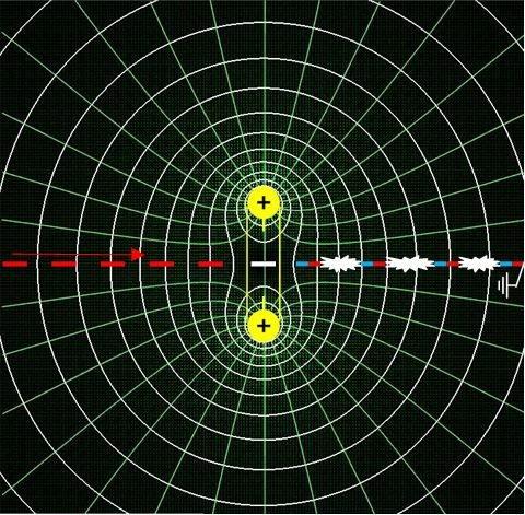 |
Figures 6: An edge-on
view of a U shaped collector is shown in yellow. Green electric field lines and
white potential lines are shown. Sector plates move from left to right.
Positively charged plates are red. Neutral plates are white. “Dipole” plates
with separated negative and positive charges are blue and red. Plasma
conduction paths are shown in white. Field and potential lines were produced
with the Electrostatics Simulator written in Java by Paul Falstad. http://www.falstad.com/
|
The geometry of the charge
collectors should be designed not only to collect charge, but also to polarize
the sector plates as they leave the collector. A common approach is to bend a
round steel rod into the shape of a U. The squared off ends of the U on typical
Wimshurst generators could be improved by rounding them off. Figure 3 shows the
squared end of the left collector emitting a dot of corona discharge which
decreases efficiency.
Mysterious
Inherent Asymmetry
R.
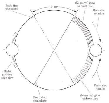
A. Ford’s observations shown in the diagram in Figure
7 reveal that the generator is not symmetrical. The plasma shape and
intensity on the negative terminal on the right is different from that
on
the positive terminal on the left.
Figure 7. R. A. Ford’s observations, taken from Publication 2,
Figure 4-55, reveal the inherent asymmetry of Wimshurst generators.
The asymmetry is due to the difference in mass between electrons
and air molecules. The Wiki article on Corona Discharge states:
“The physics of positive
and negative coronas are strikingly different. This asymmetry is a result of
the great difference in mass between electrons and positively charged ions, with only the electron having the ability to
undergo a significant degree of ionizing inelastic collision at common temperatures and pressures…. The difference, then, between positive and
negative coronas, in the matter of the generation of secondary electron
avalanches, is that in a positive corona they are generated by the gas
surrounding the plasma region, the new secondary electrons travelling inward,
whereas in a negative corona they are generated by the curved electrode itself,
the new secondary electrons travelling outward.”
Our own observations revealed that we can balance this asymmetry
by adding a wire to the negative charge collector and thus increasing the
voltage output. We used a parallel plate scale voltage meter as described by
Physics Guys at PhysicsGuy.Org. Adding a wire to the positive side decreases
the voltage output. Asymmetry can be measured by using a parallel plate scale
voltage detector where both plates are connected to the positive charge
collector. Then this is done with negative collector. Experiments show the
positive terminal has three times the voltage magnitude compared to the
negative terminal.
Many publications report a similar balancing effect where adding a
smaller ball to the positive terminal produces longer sparks which indicates
higher voltages are generated. They hypothesize that the production of longer
sparks is due to the concentrated field around the smaller discharge ball, but
there may be more to it. These observations indicate that changing the self-capacitance
of either terminal changes how well the Wimshurst generates voltage.
Here are Dr. Antônio Carlos M. de Queiroz’s observations:
“Significantly
longer sparks can be obtained by the addition of a smaller ball attached to the
positive terminal. This increases the electric field around the positive
terminal, forcing the ionization of the air to start at the positive side of
the gap, instead of at the negative side, as happens with a symmetrical gap.
The positive ionization forms a nice plume-like structure (that can be seen in
the dark) pointing away from the positive terminal, that easily gets connected
to the diffuse corona that the negative terminal emits. When the connection is
established, a spark occurs, with the electrons flowing from the negative
terminal to the positive. Short sparks are observed as bright straight lines.
Longer sparks are more irregular, and may present branches, almost always in
the direction of the negative terminal. In short sparks, the positive end is
brighter, specially in sparks obtained without added Leyden jars, due to more
concentrated current. In long sparks, the positive end is always a straight
line perpendicular to the surface of the terminal, with the negative side
irregular and a little brighter (why is a mystery).”
Verifying the Charging Mechanism
An
experiment was done to verify the plasma conduction paths between the
edges of sector plates could charge a neutralizer bar. The
metal plate of a Scale Voltage detector, described elsewhere at PhysicsGuy.Org, was charged as shown in
Figure 8. This transfer of charge confirms our hypothesis about Wimshurst conduction
paths and their role in explaining how a Wimshurst generator works.
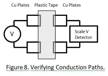 |
Figure 8. Copper foil plates were placed on a plastic board so that the edges were one cm
apart, about the same distance as the sectors on the Wimshurst disc. Even
though the edges did not touch at all, experiments proved that a current across
the air gap develops when a high voltage is applied to the plates on the left. When plastic
tape is placed over the gaps so that the edges are covered in plastic, there is
no current |
Alternative to Placing a Wimshurst Generator in a Vacuum
A Wimshurst generator could be placed in a vacuum chamber to
eliminate or reduce conduction paths. An alternative approach would be to cover the
sector plate edges on the generator with an insulating plastic as was done in
Figure 8. Publication 3 describes a Wommelsdorf Condenser Machine where this
was done. The result is the Wommelsdorf produced higher voltage and was more
efficient. Much higher voltages are needed to create conduction paths through
the dielectric plastic used in this generator. A standard Wimshurst generator
is 15% efficient and a Wommelsdorf Condenser generator is 32.5% efficient.
Plasma conduction paths are important factors in the functioning of electrostatic
generators. These
paths are formed in
air with Wimshurst generators and other types of electrostatic
generators. Covering sector plates with plastic can reduce the size and
resistance of these conduction paths, and allow the generator to
operate more efficiently at higher voltages. This is done with
Wommelsdorf generators.
The sharp edges of sector plates limit the maximum voltage and the
generator efficiency. Too high a
voltage and the generator will start to spark across the sector plates.
Asymmetry
is also a limiting factor. Efficiency can be improved by tuning the
generator
with objects of varying self-capacitance. The Wimshurst Generator is a
powerful
tool for studying the effects of plasmas generated from sparks and
corona
discharges